Saturday, 23 July 2016
Thursday, 21 July 2016
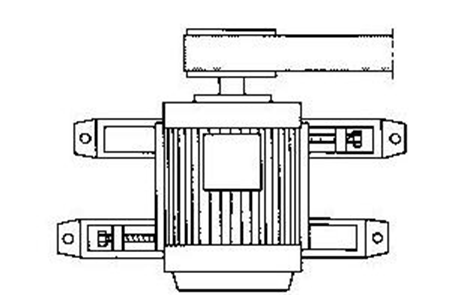
BALL BEARING
Ball bearing are found in practically any type or
size of motor. They offer low friction, can oprating at high speed and run
effectively over a wide temperature range. Modern ball bearing are well
designed for the job at hand, are made of increasingly better materials, and
last longer. Show the basic parts of a rolling – type bearing.

In the ball
bearing family the most popular assembly is the single – row deep – groove
bearing
It is a
radial load bearing, but it can also handle considerable thrust loads in either
axial direction. ( A thrust load is a pushing force against the bearing
parallel to the shaft ; radial loads is a pressing force at right angles to the shaft. Most bearings are
expected to carry both type of loads to some degree )
REMOVE BEARING
In many
instance, bearing vhane to be removed from the shaft simply to allow others parts
to be removed regrettably it often happens that bearings that are ferfect
before removeal for inspections or cleaning are damage during removal mounting.
It is good practice only to remove bearings when strictly necessary. Baring
inspections should instead be done by listening to the sound of bearing and
absering the lubricant.
A bearing which is to be reused should, for endurance life
reasons, always be
remountd in the same relative position as before. It is therefore advisable,
before dismounting, to mark the position of the bearing which side is
uppermost and which side faces the
front.
Small
and medium size bearings may be dismounted
using a conventional puller. If the bearing has been mounted with an
interference fit on the shaft, the puller should engage the inner ring.
To avoid
damage to the bearing seating. The use of a self centering puller eliminates
the risk of damage, and dismounting is simpler and more rapid. Only in one
cases where it is imposible to engange the inner ring is it permitted to apply
the puller o the outer ring. But, and this is important, the outer ring must be
rotated during dismounting so that no part of the bearing is damaged by the
dismounting force. This can be doneby locking the screw and turning the puller
continuously until the bearing comes free.
Dismounting
the inner ring of cylindrical roller bearings can be easly done with an
aluminum heating ring as shown fig.


The
dismounting procedure is simple. First remove the outer ring with the roller
and cage assembly. Coat the raceway of the inner ring with an oxidation resistant oil. Heat
ttthe aluminum ring to a temperature 121°C ( 250 ° F ), place it on the inner ring, and
press the handles togheter. Use the tool to withdraw the inner ring as soon as
it becomes loose. Remove the ring from the tool immediately. If the inner rings
have different diameters and if dismounting is frequent, use of an induction
heating tool is freferable, as shown fig.
such heaters
raise the temperature of the inner ring by inducing currents. The adjustable
heater is suitable for various inner ring diameters over 80 mm, depending on
the manufacturer of the induction heater.
Heat the
inner ring for 15 to 30 sec, until it comes loose, and the withdraw it, the
inner ring must not be heaterd o
temperature above 121°C
( 250 ° F ). Switch of the current, remove the ring from the
tool, and demagnetize it.
Use, open (
not sealed or shielded ) bearings, if
heavily coated wih oxidizes grease, must be thoroughly cleaned before use. He
bearings should be soaked in hot, light oil at 93° to 116°C ( 200° to 240° F ), gitating the basket of bearings
slowly through the oil. In extreme cases, boiling in emulsifiable cleaners
diluted with water will usually soften the contaminating sludge. If the hot
emulsions are used, the bearings should be drained and spun individually until
the water has completely epavorated and then adequately protected.
MOUNTING BEARINGS
When a
bearing is to be mounted on shaft, could or hot mounting may be used. Cold
mounting is only suitable for small bearings and bearings that do not have to
be pressed far on to the shaft. For hot mounting and where the bearing is an
interference fit on the shaft, he bearing is heated first in an oil bath or
with a special heater. It is then pressed on to the shaft a mounting sleeve
that fots the inner ring of he bearrring. Grease – filled bearings, which
usually have sealing plates or shield plate, should not be heated.
Correct mounting
Mounting method
MOUNTING PULLYS AND COUPLING
A couling
half or pulley that is a push fit on the shaft can be pushed on by hand for
about half the length of the shaft extension. A special tool or a fully
threaded bolt, a nut and two flat pieces of metal are used to push it fully
home against the shoulder of the shaft.
If there is
no tapped hole in the end of the shaft, the coupling half can be heated to 80° C and pushed on to the shaft. If the coupling half is
machined for a tighter fit than and the push fit, it mush be heated to abaouth
150 ° C. the coupling halp is locked with an end plate. To remove
the coupling half, a puller is used.
It is bad
practice to use a lead mallet when fitting pulleys or couplings, and especially
bearings he harm that can be done by such treatment cannot be over emphasized.
It causes pitting of the receways in the bearing, and this damage increases in
service, leading to savere scaling. Statistics show that some 70 % of motor
faults are ue to bearing defects, and many of these can be traced back to
mistreatment during the mounting of a coupling or pulley.
ALIGNMENT
Motors must
always be accurately aligned, and this applies especially be where they are
directly coupled. Incorrect alignment can lead to bearing failure, vibration
and even shaft fracture. As soon as bearing failure or vibration is detected,
the aligment should be checked.
Couplings
To determine
whether the shafts are parallel, measure first with a feeler gauge the distance
x between the outer edges of coupling halves at a point on the periphery : Fig
Then run both halves togheter through 90°, without changing the relative positions of shafts, and
measure again at exactly the same point. Measure the distance again after 180 ° and 270 ° rotation. For typical coupling
sizes, the difference between the highest and lowest readings must no exceed
0.05 mm.
To check
that the shaft centres are directly
opposite each other, place a steel rule parallel with the shafts on the turned
periphery of one coupling half and then measure the clearance between the
periphery of the other half and rule in four positions as a parallelism check.
The difference between the highest and lowest readings must not exceed 0.05 mm.
The best way
of achieving proper alignment is to mount a pair of dial gauges as shown in fig

Each gauge is on coupling half they indicate difference between the coupling
halves both axially and radially. By
slowly rotating the shafts while observing the gauge readings it possible to
obtain an idea of the adjustments that need to be made. The coupling halves
must be loosely bolted together so that they can easily follow each other when
they are turned.
When
aligning with a machine, the frame of which reaches a different temperature
from the motor in normal service, allowance must be made for the difference in
shaft height due to differences in the thermal expansion. For the motor, the
increase in height is about 0.03 % from ambient temperature to oprating
temperature at full output. Mounting instructions from manufacturers of pump,
gear units etc. often state the vertical and lateral displacement of the shaft
at oprating temperature. It is important to bear in mind this information to
avoid vibration and other problems in serfice.
VIBRATION
The International
Standardisation Organitation, ISO, has issued international standard covering balancing and vibration characteristics. ISO 2373
is of particular interest for electric motors. It governs permitted vibration level on delivery and applies to motors
with shaft heights in the range 80 t0 400 mm. The vibration level is expressed
in mm/s rms ( milimeteres per second root
mean squared ) and must be measured at no load with the motor on elastic
mounting. ISO 2373 requires the shaft extension to be fited with a full – size
key during vibraton measurement. The requirements apply in the measurement
range 10 to 1000 Hz.
Grade
of
|
Speed
|
Maximum
Vibration Velocity in mm/s rms
|
||
quality
|
r /
min
|
at
shaft height, mm
|
||
8 -
132
|
160 -
225
|
250 -
400
|
||
N
|
600 ≤
3 600
|
1.8
|
2.8
|
4.5
|
Normal
|
||||
R
|
600 ≤
1800
|
0.71
|
1.12
|
1.8
|
Reduced
|
> 1 800
≤ 3 600
|
1.12
|
1.8
|
2.8
|
S
|
600 ≤
1800
|
0.45
|
0.71
|
1.12
|
Special
|
> 1 800
≤ 3 600
|
1.71
|
1.12
|
1.8
|
The
corresponding standard for large machines has not yet been issued, but a figure
of 2.8 mm/s can be taken as guide, at least for squirrel– cage motors. Measurement with the motor bolted fast to a solid base
may occur, as may measurement with a half key fitted to the shaft extension,
the smooth shaft method.
Rotor
balancing is a relatively simple opration and the balance is easy to check.
However, the final vibration resistance is also iinfluenced by other factors,
mainly the nature of base on wich he motor is mounted, although the method of
clamping, the aligment and the electromagnetic forces also play part.
IMBALANCE
If a machine
that has been correctly aligned vibrates, the couse may be balance. This is
usually due to a badly balanced coupling half or pulley. If the machine is to give trouble – free
service, the coupling half or pulley must be properly balanced before it is
fitted.
Vibrations of the magnetic origin may arise as
a consequence of the fact that the air gap is not straight or because of an open or short circuit in the
windings. Vibration of this ype cannot be reduced by rebalancing the rotor.
BEARING


Types
of bearing ;
Bearing life
of rolling bearing in motors is normally 25 000 to 100 000 hours L 10 to ISO R
281. Nominal life is the number of running hours at given speed for wich the
bearing can rotate before signs of fatigue – scaling - appear on the rings or rolling elements.
ISO
definition L 10 means the length of life that 90 % of a large number of
identifical bearings are expected to reach or exceed. Half of the bearing
achieve as times the L 10 life.

VIBRATIONS
VIBRATIONS
The International
Standardisation Organitation, ISO, has issued international standard covering balancing and vibration characteristics. ISO 2373
is of particular interest for electric motors. It governs permitted vibration level on delivery and applies to motors
with shaft heights in the range 80 t0 400 mm. The vibration level is expressed
in mm/s rms ( milimeteres per second root
mean squared ) and must be measured at no load with the motor on elastic
mounting. ISO 2373 requires the shaft extension to be fited with a full – size
key during vibraton measurement. The requirements apply in the measurement
range 10 to 1000 Hz.
|
Grade
of
|
Speed
|
Maximum
Vibration Velocity in mm/s rms
|
||
|
quality
|
r /
min
|
at
shaft height, mm
|
||
|
|
|
8 -
132
|
160 -
225
|
250 -
400
|
|
N
|
600 ≤
3 600
|
1.8
|
2.8
|
4.5
|
|
Normal
|
||||
|
R
|
600 ≤
1800
|
0.71
|
1.12
|
1.8
|
|
Reduced
|
> 1 800
≤ 3 600
|
1.12
|
1.8
|
2.8
|
|
S
|
600 ≤
1800
|
0.45
|
0.71
|
1.12
|
|
Special
|
> 1 800
≤ 3 600
|
1.71
|
1.12
|
1.8
|
The
corresponding standard for large machines has not yet been issued, but a figure
of 2.8 mm/s can be taken as guide, at least for squirrel
– cage motors. Measurement with the motor bolted fast to a solid base
may occur, as may measurement with a half key fitted to the shaft extension,
the smooth shaft method.
Rotor
balancing is a relatively simple opration and the balance is easy to check.
However, the final vibration resistance is also iinfluenced by other factors,
mainly the nature of base on wich he motor is mounted, although the method of
clamping, the aligment and the electromagnetic forces also play part.
SPEED ELECTRIC MOTOR
The speed of
an a.c motor depends on the mains frequency and number of poles of the stators winding Redesign Speed in
Bahasa
n =
|
2 .
f . 60
|
. r/min
|
p
|
Where n = speed
F = frequency
P = number of poles
The rule of
thumb for 50 Hz mains frequency is that the speed in revolutions per minute (
r/min ) is 6000 divided by number of poles. This is synchronous speed ; it can never be reached by an
inductions motor, squirrelcage or slip – ring motor.
At o load, however, the speed is practically equal to the synchronous speed ;
at rated output it is slightly lower.
The
following equation s used to calculated the slip :
s =
|
n₁ - n
|
. 100 %
|
n₁
|
||
Where s =
slip in %
n₁
= synchronous speed, r/min
n =
asynchronous speed, r/min
the slip is proportional to the power
taken from the motor.
Example
4 – pole motor, 4 kW, 380 V, 50 Hz,
1425 r/min
At 4 kW ; s =
|
1500 -
1425
|
. 100 %
|
1500
|
||
s = 5 %
corresponding
to 1500 – 1425 = 75 %
At 3 kW : s =
|
1500 -
1425
|
. 100 %
|
||||||||
1500
|
||||||||||
s =
|
3
|
.
|
1500
- 1425
|
r/min
|
.
|
100
|
3.80%
|
|||
4
|
1500
|
|||||||||
Corresponding
to :
3
|
.
|
1500
- 1425
|
r/min
|
=
|
56
|
r/min
|
4
|
Therefore n
at 3 kW will be 1500 – 56 = 1444 r/min
This slip is
inversely proportional to the square of the voltage
Example
4 – pole motor, 4 kW, 380 V, 50 Hz,
1425 r/min. Supply Voltage 346 V, 50 Hz
At
346 V
|
s =
|
(
|
380
|
)
|
²
|
.
|
1500
- 1425
|
.
|
100
|
=
|
0.6 %
|
346
|
1500
|
||||||||||
Corresponding
to :
At
346 V
|
s =
|
(
|
380
|
)
|
²
|
.
|
(
1500 - 1425 )
|
.
|
=
|
90
r/min
|
346
|
n will therefore be 1500 – 90 = 1410 r/min
The rules
above apply to moderate changes in output voltage. The speeds of the motors
when warm and at rated output are subject to a tolerance of ± 20 % of he slip. The normal testing speed for overspeed is
120 % of the rated speed for two minutes.
poles
|
synchronous speed at
|
|
50 Hz
|
60 Hz
|
|
2
|
3000
|
3600
|
4
|
1500
|
1800
|
6
|
1000
|
1200
|
8
|
750
|
900
|
10
|
600
|
720
|
12
|
500
|
600
|
16
|
375
|
450
|
20
|
300
|
360
|
24
|
250
|
300
|
32
|
18,5
|
225
|
48
|
125
|
150
|
Subscribe to:
Comments (Atom)